Showing posts with label HAM Radio. Show all posts

Saturday, June 20, 2015

50 Ohm Resistor Networks for Dummies


It's called a dummy load. No seriously, it is.

What's it for? Well, it gives the radio a place to send its power without radiating RF.

Why? It provides a nice consistent load for tuning the final amplifier stage on my radio before I transmit. It can also be used for testing the radio after a repair. Also, some radios transmit while receiving a program download from a computer (though they shouldn't.) This gives you a way to prevent such transmissions from interfering with others.

Why not just disconnect the antenna? Well, the radio forms one half of a resonant circuit. The antenna forms the other half. The most efficient circuit is one where both halves have the same impedance. For amateur radios, that ideal impedance is fifty ohms.

If you have an impedance mismatch, not all of the energy makes it from the transmitter to the antenna. The law of conservation of energy says that the energy that doesn't make it to the antenna has to go somewhere, and in this case, it gets reflected back to the radio. When it gets back to the radio, it gets turned into the heat in the final amplifier stage. Enough heat, and the radio dies.

As far as impedance mismatches go, a disconnected antenna is about as bad as you can get. That's why you should never run a radio without an antenna attached. When you fire up the transmitter, all the energy goes to the antenna connection, and finding nothing there, is reflected right back to the final amplifier. Since all the output from the radio gets instantly turned into heat, failure happens pretty quickly. The 50 ohm dummy load gives the power a place to go. It still gets turned into heat, but the heat is in the dummy load instead of the radio. And the dummy load is built to shed heat.

My dummy load is a network of 1k ohm resistors in parallel. The net resistance of this network is 50 ohms. The resistors are each able to dissipate 3 watts of power, so together the network can handle 60W.

However, my VHF radio is capable of putting out 75W, and my HF radio can pump out 100W. So, the resistor network sits in a 1L paint can filled with mineral oil. This will allow the resistors to take more heat before failing.

This build is based on a design by K4EAA. He also sells the pack of resistors needed to build it. (Not just any resistors will work, since some are built of a coil of wire. Such wire-wound resistors are OK for DC, but as soon as you pass RF through them, they act like inductors instead of resistors, and their impedance changes. These are metal-film resistors which have the same impedance at any frequency.)

Now, if only I could remember to switch back to the antenna after tuning the finals...

Wednesday, June 17, 2015

Hot Tubes in the Shack

These days, there's a ridiculous number of directions one can take in the hobby of amateur radio. But in the beginning, "amateur radio" meant someone banging out Morse Code on medium wave or shortwave.

Shortwave (HF) is the bread and butter of amateur radio. Before there were satellites, before transoceanic cables, people were using HF radios to communicate across the world. And they still do, since HF signals can get from their source to their destination without any equipment in between.

The main drawback is that the propagation of HF radio waves around the world is heavily dependent on atmospheric conditions. And this is where the challenge lies.

Since shortly after I got my license, I've been wanting to play with HF. I scored well enough that my license permits transmission on all the amateur bands. However, an HF rig isn't cheap. I'd need at least a few hundred dollars for a basic used rig, and with everything else that's going on right now, that just isn't in the cards. 

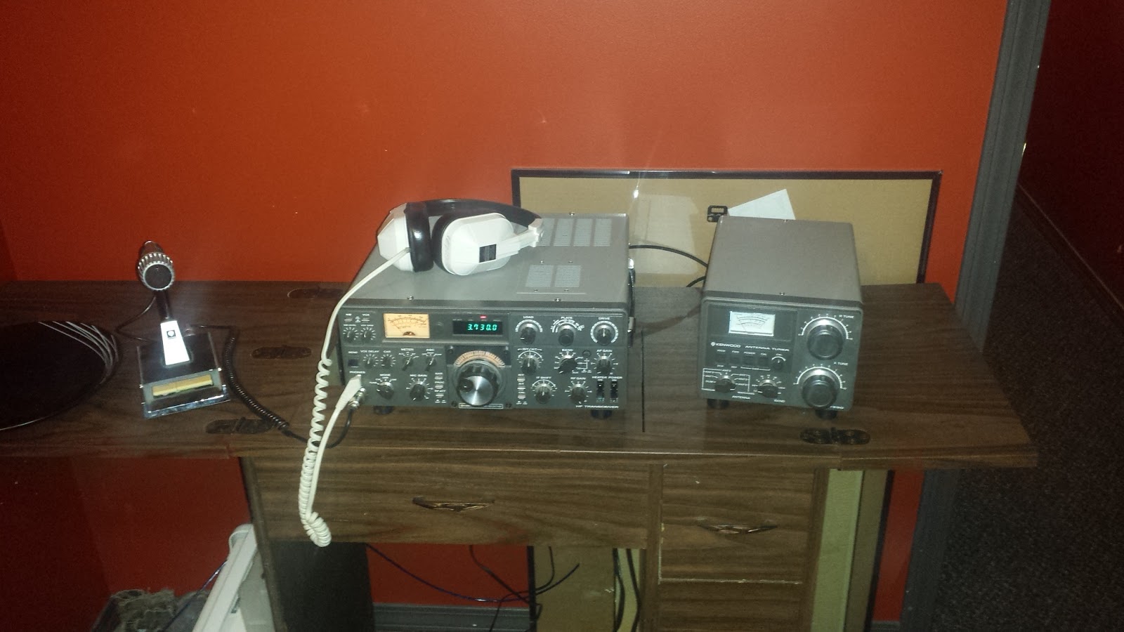
Enter the community. My situation came up in passing during a discussion over our weekly lunch meeting, and a fellow operator was more than happy to loan me one of his old rigs that had been languishing in his basement for some years. The following week, I helped him lug a Kenwood TS-530S and an AT-230 antenna tuner from his pickup to mine.

The tuner is especially important to my situation, and I'll get to it in a moment, but first I want to yak about the radio itself. Kenwood built these radios throughout the 1980s (I can't find a date stamp on my particular unit so I don't know when exactly it was manufactured.) They're what's called a hybrid rig, meaning that most of the electronics are solid state, but it uses vacuum tubes rather than transistors for the final RF amplifier (the part that puts the power out to the antenna).

Kenwood hybrid final compartment. Photo courtesy of k4eaa.com
Vacuum tubes have been largely replaced by transistors, even in ham radio, because they don't consume as much power, are smaller, and last longer (tubes have a lifespan, much like light bulbs, and radios using tubes are designed so that the tubes can be easily replaced.) However, tubes still find their uses in large RF power amplifiers, microwave ovens, audiophile amplifiers, etc.

The Kenwood hybrids are sought after among the ham community. (As an example, I recently found an eBay listing for a TS-530S selling for $300CAD - and it's broken.) While they're a simple rig, lacking many of the features in modern digital radios, they make up for it by being easy to use, robust, and easy to repair. The radio's much larger and heavier than a modern radio of equivalent functionality, but large discrete components are easier to remove and replace if something goes wrong.

It's actually a perfect starter rig for a ham just getting into HF.

For starters, it doesn't feel like a toy. I had an opportunity to use an Elecraft KX3 recently, and it wasn't much bigger than my handheld. The Kenwood lets you know that it means business. It's twenty kilos of radio sitting on my desk.

The other thing that makes it perfect for a starting ham is that it's all manual. The most modern thing about this rig is the digital frequency readout. There's no automatic antenna tuner, and you have to tune the final amplifier stage whenever you switch frequency bands. Having to learn about all this stuff teaches you things about how radios are built, and how signals propagate through your antenna and through the air. Things that you won't learn on a modern rig like an Elecraft K3. Don't get me wrong; I'd love to have a K3 in my shack, but it's like giving a calculator to a fourth-grader before teaching them long division. There's always the risk that they'll take the easy way out, and miss an important learning opportunity.

And learning is the reason that I got into ham radio in the first place.

Of course, this radio isn't without its drawbacks. For me, the biggest one is the lack of portability. Between being physically large and heavy, and being power-hungry, this rig isn't going camping with me. My goal of contacting hams on the other side of the world while sitting next to a campfire by a lake in the bush will have to wait until I can afford a smaller rig like the Yaesu 817D or an Elecraft KX3. However, for now, that's more than made up for by the fact that I'm on the air, with nothing more than a piece of clothes line strung between my house and my shed.

And that's where the tuner comes in. A radio and its antenna each form two halves of a resonant circuit, and to maximize power transfer from one half to the other, each half must have the same impedance. Since the impedance of an antenna is a function of the length of the antenna and the frequency of the signal, (this is an oversimplification, but it works for my purposes,) antennas have to be constructed with the proper length and spacing in order to work. Any random length of wire usually won't do, because it will be too long or too short, and this will cause RF energy to be reflected back to the radio. This reflected RF energy gets turned into heat in the radio's final stage, which eventually burns it out.

The tuner makes up for a badly tuned antenna by adding additional resistance or reactance to the antenna side of the resonant circuit so that it appears to be perfectly matched to the radio. This allows the radio to push maximum power to the antenna without risking damage. The drawback is that, since the antenna isn't truly resonant, some amount of transmitted power is soaked up by the tuner. The further out of tune the antenna is, the more power is wasted.

The silver lining of this cloud is that a tuner allows an operator to use any random length of wire as an antenna. It's not as efficient as a tuned antenna, but it gets my signal out into the air without risking letting the magic smoke out of my borrowed tubes. Twenty bucks worth of clothes line and a couple screw-in anchors has me talking to folks a few hundred kilometers away.

Wednesday, February 25, 2015

Tuning my first antenna

So, I done gone and built my first antenna.

It's a simple directional antenna called a "yagi", designed to operate in the 2 meter amateur band (144-148MHz). The plans came from this QST magazine article. So far I'm out about $14 in parts and a couple hours' labor. (The plans are titled "7dB for seven bucks"; I chalk up the discrepancy to inflation and currency conversion).

The antenna works like this: there are three wire elements attached to a non conductive boom. The center element is the driven element; it is connected to the radio and is driven by it. The other two elements are called parasitic elements because they are not electrically connected to anything; they work by absorbing and reflecting the field produced by the driven element.
The longer element is called the reflector and the shorter one is the director. They work together to focus the field produced by the driven element, stretching it out along the axis of the boom and compressing it along the sides, in much the same way lenses and mirrors can be used to shape the light coming from a lamp.

But just like a musical instrument, building it is only half the job. Because an antenna is part of a resonant circuit, it must be tuned to match the radio to which it's attached. And the resonance changes with frequency, so the antenna must be tuned for the frequencies on which it will be used.
Now, I don't want to dive into a lot of electrical engineering here, partly because I don't completely understand it myself, so the short story is that a good measurement of how well your antenna is tuned is something called the standing wave ratio. Basically, if the antenna is out of tune, some of the power sent to it will be reflected back to the radio. The further out of tune, the more power is reflected. Too much reflected power will overheat and burn out the radio. The SWR is the measurement of how much power is reflected.

The resonant frequency is controlled by the length of the driven element. So tuning the antenna means changing the length of the driven element until the antenna resonates at the frequency you want. Since it's hard to make wires longer, I started with an antenna that was too long and trimmed the elements as necessary.

So how do you measure SWR? Why, with an SWR meter of course! Trouble is, I don't have one. However, a fellow operator was kind enough to lend me his antenna analyzer, which not only measures the SWR, but also the impedance, capacitance, inductance, and many other things. Since this is my first antenna, I'm not too worried about these things; I'm mainly concerned with building something that is an improvement over what I already have, without blowing up my radio, and an SWR below 2 will do that for me.

So I stood the antenna up on a step ladder in my back yard, hooked up the analyzer, and started tuning. Initially, the antenna resonated at about 130MHz, which is too low. I began trimming the driven element in 1/8" and 1/4" increments until I eventually got the antenna resonating at about 145MHz with an SWR of 1.6. This puts it nicely in the 2 meter amateur band.

How good is this? Well, before I packed everything away, I hooked the analyzer to the factory-built magnetic whip I have (A magnetic whip is an antenna which is magnetically stuck on the roof of your car). It resonates at 162MHz, has an SWR of 2.9 at 144MHz and an SWR of 2.4 at 148MHz. That doesn't sound very good, but if I were to give the manufacturer the benefit of the doubt, I would say that the poor readings are the result of the fact that a magnetic mounted antenna uses the surface to which it's stuck as a ground plane, which means it relies on a good electrical connection, something that is dependent on the type of paint used on the car (non-metallic paints will provide a poor electrical connection, which will hurt the antenna's efficiency.)

So while it's not the best antenna around, I'd say it's a good first try. Mainly I did it for the learning experience, and for that it was wildly successful, as it taught me an important lesson about antenna-feedline interaction:

The feedline gets in the way, electrically speaking. I originally had the coax feedline hanging down the mast in the center, which puts it inline and near to the driven element. On the advice of a fellow operator, I routed the feedline along the boom to the rear. This meant the coax was now running perpendicular to the antenna elements instead of parallel to them, which had a significant impact on resonance, impedance, and SWR. Future designs will take this into account from the beginning.

Thursday, February 12, 2015

Portable shack: Powering up

I needed a power supply for my Yaesu mobile. Often times, such as when programming,  I find myself wanting to power up the radio in the house. However, since the radio is designed to run in a car, it wants 12 volts DC. 
To maintain flexibility, I've wired the Yaesu with an Anderson connector, and built a cable to plug into a car cigarette lighter socket. This allows me to drop it into a car easily. For use inside the house, I have a power supply from an electric cooler, which plugs into the wall and supplies 12 volts to just such a socket. 
However, this power supply isn't up to the task of supplying the current necessary to drive the radio at full power; I can turn the radio on and program it, but if I try to transmit at anything above minimum power, the little power supply shuts down. 

Now, lucky for me, a computer power supply can also supply 12 volts. And depending on the unit, it can supply quite a lot of power. But you can't simply plug a radio into a computer power supply.
For starters, the plugs don't match. The power supply has many special connectors for the computer motherboard, drives, etc., while the radio uses a different connector. (in my case, an Anderson SBS connector that I'd scrounged.)

Secondly, while this power supply is able to deliver 10 amps on the 12V rail, none of the components connected to it need that much current all by themselves. Thus, the power supply has several 12V wires going to different places. The radio, on the other hand, wants that 10A all to itself, which makes these little wires less than optimal, (and probably a fire hazard.)

And finally, there are a lot more wires than I need. The power supply can not only deliver 12V, but can also deliver 5V and 3.3V, for other uses inside a computer. The radio doesn't need any of these other voltages.

This is a power supply I rescued from a computer destined for the recyclers. The first thing I needed to do was remove the rat's nest of wires hanging out the back. To keep things clean, I wanted to desolder everything from the board and replace it all with a single Anderson SBS connector. Fortunately, the holes in the board are large enough to accept the 10 guage wire that's on my connectors; the challenge was finding a soldering gun large enough. The wires themselves will carry heat away from the joint, so you need a gun large enough to put heat into the joint faster than the wires can carry it away. A torch would do the trick, but it would also burn the board.

Once I had removed all the wires, I soldered the Anderson connector onto the board. There's just enough wire to carry the connector outside the case, where I could bolt it to the chassis (as a strain relief.)

The next task was to provide a way to turn the power supply on. This is an ATX power supply, which means it's normally controlled by the computer. The computer is able to turn itself on and off, but it also means that there isn't a switch on the power supply; there's no way to turn it on unless it's connected to a computer.

Well, a little research on the internet showed me that if you tie one of the wires to ground, the power supply will come on, and breaking that connection will turn the power supply off. So I drilled a hole in the back of the case, installed a toggle switch, and connected it between this lead and ground.

This power supply is able to drive my Yaesu at full power (75 watts) without any problems. It supplies just a shade under 12 volts, which is less than the car, but the radio doesn't seem to mind. 

Friday, February 6, 2015

Portable Shack: The Next Generation

My first design for a portable radio shack has died on the drawing board.
After a bit of thinking, I decided that a single box to contain all my radio gear would simply be too big. Starting with a 30kg battery and adding a few radios would have resulted in a box that was just too much to haul around in a practical manner.

Instead, inspired by the design of the case for the Spilsbury SBX-11 that was given to me by a friend, (similar to the one pictured on this page,) I decided to build a case for each radio, and one more for the battery. In addition to making it easier to pack everything, since it's easier to move several small boxes than one huge one, it also provides more flexibility. For example, if I'm going on a short road trip, I can take the 2m mobile and plug it into the car's power outlet instead of lugging around a bunch of extra stuff (battery, HF radio, antennas, etc,) that I won't need.

Well, I just finished the first of these cases. It's designed to hold my Yaesu FT-2900R 2m mobile radio. The box is constructed of 3/8 plywood, rabbetted and joined with glue at the seams. Inside the case are several ripped-down pieces of lumber which act as spacers, so the radio is held snugly in the case while allowing room for air circulation. There's a space behind the radio so the antenna cable has room to turn around and exit via the front opening without getting damaged.
The microphone hanger is attached to the lid of the case, so that the mic can be stowed inside the lid when not in use. The case is waterproofed, so it can be left out in the rain without risking damage to the radio. (The only thing left to accomplish this goal is to add a gasket to the lid seam.)
I've made the wiring connections as modular as the case design. The power cable is short, fused, and terminated with an Anderson SBS connector. It will be connected to a longer cable which will supply power from a battery, or a car's power outlet; using the Anderson connectors means I can build different cables for each power supply application, and interchange them between my radios. I'm also going to get a small extension for the antenna line so that I can connect an external antenna from the front, instead of having to remove the radio from the box each time I set it up and take it down.

With this setup, I can set up a station nearly anywhere, in only a couple minutes. It's even suitable for dropping into a vehicle to provide mobile service, as long as I don't have a front passenger. And while it's not as portable as my handheld, it also has fifteen times the output power, so I can see it being taken to a lot more places now that it has a nice-looking overcoat.

Wednesday, February 4, 2015

Chasing RFI: The Workaround

The only thing better than seeing a project through to its conclusion is not having to do the project at all.

I had been reading this document, which does a very good job explaining RFI, while I tried to find some time to hunt down the source of the interference in my house. While I was doing that, the good folks who brought us CHIRP made some improvements to the software that allow me to expand the squelch range on my Baofeng GT3, which meant I could cut out the bursts of static while still hearing actual signals.

"But hold on a sec," you say, "what exactly is this squelch thing you're talking about?" Squelch is a circuit in a radio receiver that turns off ("squelches") the audio when a signal is not being received. When a strong enough signal is detected, the "squelch is opened" - the audio circuit is turned on so you can hear the received signal.

Not all radios have a squelch circuit, but the ones that do (all that I've seen at least,) have an adjustment. This allows you to set the strength of signal that is required before the squelch opens. Ideally, you want to adjust the squelch to be low, so that you don't miss a transmission. However, there are times when you need to turn it up, such as when you're in an area with a lot of RF noise.

The problem with the UV5R series of radios (of which my GT3 is a member), is that the squelch is notoriously useless. Bursts of static will trick the radio into thinking that there's a signal present when there isn't one, and the squelch adjustment is very narrow (there is no noticeable difference between level 1 and level 9).

So, back to CHIRP. The 10 levels of squelch available in the GT3's menu (0 thru 9) are mapped to values inside the radio's programming. In fact, the radio can set the squelch anywhere between 0 and 127. At the factory, the 10 levels in the menu are mapped to these internal values.

Once I installed the latest daily build of CHIRP and looked at the squelch mappings on my radio, I discovered that levels 1 thru 9 (0 is mapped to 0, which disables the squelch circuit altogether) were mapped to values between 17 and 33, in increments of 2. On the advice of this page on the Miklor website, I changed the values to range between 24 and 64, in steps of 5.

After dumping the modified image to my radio, I moved to a part of the house where I previously had static. I turned the squelch up one step at a time until the static stopped. While I was doing this, a couple other folks were having a conversation on the local repeater that I was monitoring. I was able to confirm that my new squelch setting got rid of the static while still letting the signal from the repeater through.

So my time-consuming hunt for RFI sources has been called off. And a good thing too, since I have a bunch of other projects on the go, and I don't really have the time to go chasing RF gremlins.

Monday, January 5, 2015

Chasing RFI: Introduction

If you've been following along, you'll remember one of the reasons I'm building a portable RF shack is that my house is full of RF interference which is causing me problems. I'm going to try and track down the source of the interference, eliminate it if I can, and hopefully learn a bunch of stuff along the way.

Right now I'm in the very early stages of troubleshooting. Shortly after I got my handheld (a Baofeng GT3 Mk2) I noticed that it would break squelch in certain areas of my house while tuned to the local 2m repeater. When the squelch opens, all I hear is static.

My first thought was that some piece of computer gear was causing the interference, so one morning while everyone else was asleep, I tried to do some rudimentary investigation. I placed my radio in a location where it was picking up the interference, then I shut down my server, and cut power to my network stack. The noise went away. A little further experimenting pointed me to the ethernet switch.

However, changing the switch to a different model resulted in the same interference. Also, it seems that the interference is only present if there's an ethernet device connected to the switch.

A little later on, a friend of mine loaned me his SDR (software defined radio). I plugged it into my computer, installed HDSDR, and took a look at the waterfall display. I could easily see signals present all through the 2m amateur band, spaced at something like 30-50Khz intervals. Reading on the internet doesn't point me to any definite sources.

At this point I'm devising some more rigorous scientific testing so that I can conclusively narrow down the source of the interference. I'll post the results of my experiments here, so stay tuned.

Why a portable shack?

While I would love to have a fixed station in my house, I'm coming up with more and more reasons to forsake the basement radio room for a portable radio shack.

That's not to say that I won't use my radios at home, but I think I'm going to be doing more with the radios while out of the house than in it, and it's easier to accomodate the portable shack at home than it would be to take a permanent station on the road with me.

For starters, I don't have the space in the house to dedicate to a bunch of radio gear. While there are many places where I could set up a radio rig, they all get used for something else at some point. This means having a shack I can set up and take down easily is important, and then I'm halfway to a portable unit already.

Secondly, I don't have the space outside the house for a long antenna. We live on a city lot with neighbours on all sides. Our back yard is completely open; any mast would stick out like a sore thumb.

Thirdly, my house is full of RF trash. I'm going to do some work to narrow down the source and try to filter it out, (stay tuned for more on that,) but the simplest answer is just to get out of the house.

Of course, there are downsides to going portable. I'm going to be limited in power since I'm designing everything to run off a 12V battery. Since I'm not lugging a generator around, I'll be limited in the time I can spend on the air. I'm also going to be limited to portable antennas.

But then again, those limitations present some interesting engineering challenges.

Tuesday, November 18, 2014

A Portable Ham Shack for DXing on 2m

The title of this post sucks, but it's what I've got for now.

Ham radio is a multi-faceted hobby. There are just so many things you can do with a radio set and some math.

One of the things ham operators like to do is try to make contact with other stations that are far away, something known as "DXing" (in radio jargon, "DX" means "distant station"). The farther away a contact is, the better.

The weapon of choice for hunting distant contacts is usually an HF radio. This is because the HF bands (between 3 and 30MHz) will reach around the world thanks to the fact that the radio waves will skip off the ionosphere. This allows an operator to effectively bend his or her signal around the curve of the Earth.

My problem is that I don't have an HF set, and there's currently no room in my budget to buy one. So while my wife is pleased that she won't have to put up with a radio shack in the basement and the backyard suddenly sprouting a forest of antennas, I'm not going to be DXing over HF anytime soon.

However, there is another possibility. Many operators are talking to distant stations on VHF radios, in the 2m band. While the range is not as great (VHF signals punch right through the ionosphere, so they won't reach the other side of the planet,) operators are reporting contacts as far away as 1000km thanks to other atmospheric effects like tropospheric ducting.

I already have a pretty good VHF set, which I was thinking of installing in my RV trailer. However, that's going to limit me in terms of when and where I can use it (for example, I won't be using it in the winter and if we're camping, I can't get out of everyone's way to go play with my radio.) Ideally, I'd like something a little more portable so I can lug it up to a nearby mountaintop when I'm out camping. And since I'm not using HF, I don't need a huge antenna, so a portable radio shack is not out of the question.

Most portable VHF radios find themselves mounted in a vehicle. For various reasons, that won't work for me, so I'm thinking of building a portable radio shack. Basically, a box that can be lifted into or out of the back of a pickup truck by one or two people. It would house a radio (or eventually two), battery, and have space to store a portable antenna. A place to put a 20W solar panel would also come in handy and would make the rig ideal for emergency situations.

As for the antenna, my early research is pointing me in the direction of a Yagi-Uda. Something that I can easily disassemble to store inside the box. Same for the mast; I want some height, but it also needs to be portable (ideally, stowed in the box beside the antenna.) This means flimsy; hopefully I can come up with something that can be attached to the side of a vehicle for stability.

HAM N00b

Last week, I became a ham radio operator.

Some people may ask, "why the heck would you wanna do that?" Well, there are a few reasons.

For starters, I'm a geek. I'd gone pretty much as far as I wanted to go with photography, and I needed another hobby that would give me reason to read books and absorb information. In comparison to other hobbies, (like say, restoring a car,) amateur radio has some real benefits. It takes up less space. At least, for now. It can (mostly) be done indoors, which is very helpful during the cold winter months. There's less of a chance I'll find myself laying under a car in the mud trying to force stubborn pieces to fit together. And overall, it doesn't cost as much. Again, for now.

Secondly, I like math. And while there's bucketloads of math in everything we do, a lot of it seems to have concentrated itself around radio. And it's the special kind of math, made of imaginary numbers and black magic that makes your head want to turn itself inside out. All of that math boils down to how long to make a certain piece of wire and where to put it so that you can talk to another geek on the other side of the planet. That may sound condescending, but it's not. Geeks are awesome. Without geeks, we wouldn't have cell phones. Or the internet. Which means we wouldn't have Angry Birds or Candy Crush, but it also means we wouldn't have a man-made object drilling holes in a comet.

And then, there's the Zombie Apocalypse. Or ice storms. Or aliens. Or anything else you can think of that can cause a large-scale disruption of the infrastructure that makes civilization work. One of the reasons the government sets aside portions of the radio spectrum for the use of amateur operators is that, given time and geeks being what they are, eventually a communications network springs up that is completely independent of any commercial venture. This comes in handy when those commercial networks fail, such as when a car crash on the highway knocks out a fiber optic cable. Or an ice storm brings down power lines and leaves whole communities without electricity for weeks at a time.

It also comes in handy when someone is lost out in the bush, where there's no cell service and the mountains are too close together to get a signal to a satellite phone. These are places where industry has no need to build a communications network because normally there isn't anyone out there to use it.

For all these reasons, and more, I wrote my test and got my ham license.

Now it's time to start learning.